
Insights
Data Center & Critical Power Electrical
A data center is judged on a single question: does the load ever lose power? Answering no requires a deliberate stack of redundancy, from the utility feed through UPS and generators to the rack. This is a working contractor's guide to critical power topologies, the redundancy concepts behind them, and how the electrical scope is built and commissioned to earn its uptime.
What critical power means in a data center
Critical power is the electrical infrastructure whose job is to keep computing and cooling load energized without interruption, regardless of what happens upstream. In a commercial building a momentary outage is an inconvenience; in a data center a sub-second dropout can crash servers, corrupt storage, and trigger cascading failures across dependent systems. The entire discipline of critical power exists to make loss of the utility a non-event, absorbed by the infrastructure and invisible to the load.
That reliability is built from three ideas working together: an uninterruptible source that bridges the instant between utility loss and backup generation, a standby generation plant that carries the load for the duration of an outage, and a distribution system with enough redundancy that any single component can fail or be taken out of service without dropping the load. Each layer covers a different failure and a different time scale, from milliseconds to hours, and the design intent is that no single event at any layer reaches the servers.
Because downtime is measured against the total hours in a year, the targets are demanding. Five nines of availability, 99.999 percent, allows only about five minutes of downtime per year across everything: utility events, equipment failures, and maintenance. Meeting that number is not achieved by buying better equipment alone; it is achieved by the topology, the redundancy, and the ability to maintain the system while it stays online. Those are electrical construction decisions as much as design decisions.
Redundancy topologies and the Uptime Institute tiers
Redundancy is described with a shorthand that every data center stakeholder should read fluently. N is the capacity required to carry the full load with nothing to spare. N+1 provides one additional component beyond need, so any single unit can fail or be serviced and the remaining units still carry N; a UPS plant needing four modules is built with five. 2N is full duplication, two complete and independent systems each capable of the entire load, so an entire distribution path can go down with a mirror ready to carry everything. 2N+1 adds a spare component within a fully mirrored architecture for the most demanding environments.
The Uptime Institute tier classification maps these ideas to outcomes rather than to a specific parts list. Tier I is basic capacity with no redundancy. Tier II adds redundant capacity components. Tier III requires that the site be concurrently maintainable, meaning any component or distribution path can be removed from service for maintenance without affecting the load, which in practice demands N+1 capacity and multiple distribution paths with one active. Tier IV requires fault tolerance, meaning any single unplanned failure, including a distribution path, is sustained without impact, which drives fully independent 2N systems with continuous cooling.
The important distinction is between concurrent maintainability and fault tolerance, because they justify very different budgets. A concurrently maintainable site can be worked on safely but may be vulnerable during that maintenance window; a fault-tolerant site tolerates an unplanned failure even while maintenance is underway. Owners choose a target based on what an outage costs their business, and that choice ripples through the entire electrical design, the number of transfer switches, the arrangement of the UPS and generators, and the routing of every feeder.
UPS systems, static transfer switches, and energy storage
The uninterruptible power supply is the layer that makes an outage seamless. A double-conversion UPS continuously rectifies incoming AC to DC and inverts it back to clean AC, so the load is always fed from the inverter and there is zero transfer time when the utility fails; the stored energy simply keeps the DC bus alive while the generator starts. The UPS also conditions power, isolating the load from sags, surges, and harmonics that would otherwise reach sensitive electronics.
The energy storage behind the UPS is a design choice with real operational consequences. Valve-regulated lead-acid batteries are the traditional option, inexpensive but heavy, space-hungry, and demanding of temperature control and periodic replacement. Lithium-ion has become common for its smaller footprint, longer life, and better monitoring, at higher first cost. Flywheel storage offers a maintenance-light, long-life ride-through measured in seconds, well matched to sites with fast-starting generators where the battery only ever needs to cover the start-and-transfer window. The right choice depends on required ride-through time, footprint, and how quickly the generation plant can pick up load.
Static transfer switches complement the UPS by switching a downstream load between two independent power sources in a few milliseconds using solid-state devices, fast enough that the load never sees the change. In a dual-path architecture, an STS lets single-corded equipment benefit from two upstream sources, drawing from a preferred feed and shifting to the alternate the instant the preferred source degrades. Together the UPS and STS ensure that neither an upstream disturbance nor a source failure ever becomes a load event.
Standby generation, paralleling, and fuel systems
The UPS buys time; the standby generation plant provides endurance. On loss of utility, generator sets start, reach voltage and frequency, and pick up the load before the UPS energy storage is exhausted, then carry the facility for as long as the outage lasts. Sizing has to account not just for the IT load but for cooling, which is a large and non-negotiable part of a data center's demand, since computing equipment that keeps running while cooling fails will overheat within minutes.
Most sites of any scale parallel multiple generators onto a common bus rather than relying on one large machine. Paralleling switchgear synchronizes the sets, shares load among them, and applies N+1 or 2N logic at the generation layer so a set can fail to start or be pulled for maintenance without losing capacity. It also manages load steps, adding cooling and mechanical load after the critical load is stable, and can shed non-essential load if a machine drops, all automatically and within the ride-through the UPS provides.
Fuel is the constraint that defines how long the endurance actually lasts. On-site diesel storage, day tanks, transfer pumps, and a maintained fuel-quality program determine the run-time, and many operators specify a fuel supply and refueling contract sufficient for extended outages. The generation plant, its controls, and its fuel system are a coordinated assembly, and its reliability is proven the same way the rest of the system is: by testing it under real load, not by trusting the nameplate.
Distribution, monitoring, and the path to the rack
Downstream of the UPS and generators, critical power is distributed to the white space through power distribution units and, increasingly, overhead busway. A PDU takes the upstream feed, often transforms it to the utilization voltage, and breaks it into branch circuits feeding the racks, with metering at the panel and frequently at each outlet. Overhead busway has become popular in high-density and rapidly changing environments because it lets circuits be added, moved, or resized by clipping a tap-off box onto an energized bus, without the conduit and wire pull a hard-wired approach would require.
Redundancy is carried all the way to the cabinet in a well-built site. Dual-corded servers draw from two independent PDUs fed from two independent UPS and distribution paths, the A and B feeds, so the loss of an entire distribution side leaves the load running on the other. Preserving that separation is a construction discipline as much as a design one: the A and B paths must stay physically and electrically independent from the switchgear down to the rack, and the temptation to cross-tie or share a raceway for convenience is exactly what defeats the redundancy the owner paid for.
Monitoring ties the whole system together and is essential to actually realizing the designed reliability. Power monitoring and a data center infrastructure management platform track load, capacity, and branch-circuit utilization in real time, so operators know how much headroom each path has and never unknowingly load a system past the point where it can still lose a component gracefully. Metering at the PDU and outlet, breaker status, UPS and generator telemetry, and alarm reporting turn a redundant design into a system operators can trust and maintain.
How H&M approaches data center critical power
H&M Electric builds critical power for technology and mission-critical facilities across Washington, and we treat these projects as the coordination and documentation exercises they are. We self-perform the feeders, distribution, and equipment interfaces from the service entrance through the UPS and generator plant to the PDUs and busway at the rack, and we build the A and B path separation that redundancy depends on so the independence survives from the switchgear to the cabinet rather than getting compromised in the field.
We plan the outages, temporary power, and phased cutovers that data center and mission-critical work demands, and we coordinate closely with the mechanical trades because cooling is part of the critical load and cannot be an afterthought in the generator and distribution sizing. We build to the redundancy topology the owner specified, whether N+1 for a concurrently maintainable site or 2N for a fault-tolerant one, and we support the commissioning process through its levels, from factory and site acceptance testing to integrated systems testing under simulated load. As an IBEW-signatory contractor with 24/7 emergency response, we bring both the manpower for a fast-track build and the discipline the load requires.
If you are planning a data center, a mission-critical facility, or a high-density technology fit-out and want an electrical contractor who understands what N+1, 2N, and concurrent maintainability actually mean for the installation, reach out. We are glad to walk a design and construction team through the constructability of the topology and the path separation before the gear is released.
Critical power capabilities
From the service entrance to the tap-off box at the rack, H&M self-performs the scope that keeps a data center's load energized through any single event.
Redundant distribution paths
Independent A and B feeds kept physically and electrically separate from switchgear to cabinet, so an entire path can go down without dropping the load.
UPS & energy storage
Double-conversion UPS installations with lead-acid, lithium-ion, or flywheel storage matched to the required ride-through and the generator start window.
Standby generation & paralleling
Generator feeders and paralleling-switchgear interfaces built with N+1 or 2N logic, sequenced load acceptance, and fuel-system coordination.
Static transfer switches
Solid-state transfer that shifts single-corded loads between two sources in milliseconds, so a source failure never becomes a load event.
PDUs & overhead busway
Power distribution units and tap-off busway metered at the panel and outlet, ready to add or resize circuits in high-density white space.
Commissioning support
Coordination through factory, site acceptance, and integrated systems testing under simulated load, with records that prove the redundancy works.
- Serving Washington since
- 1993Serving Washington since
- Emergency response, within one day
- 24/7Emergency response, within one day
- Availability the topology targets
- 99.999%Availability the topology targets
- Fully fault-tolerant power paths built
- 2NFully fault-tolerant power paths built
Related work
All projectsTelecom switch & data center electrical
Critical-power electrical for a telecommunications switch and data center, plus ongoing service-division support.
 Technology & Evolving Industries
Innovation laboratory — LED environment & lab TI
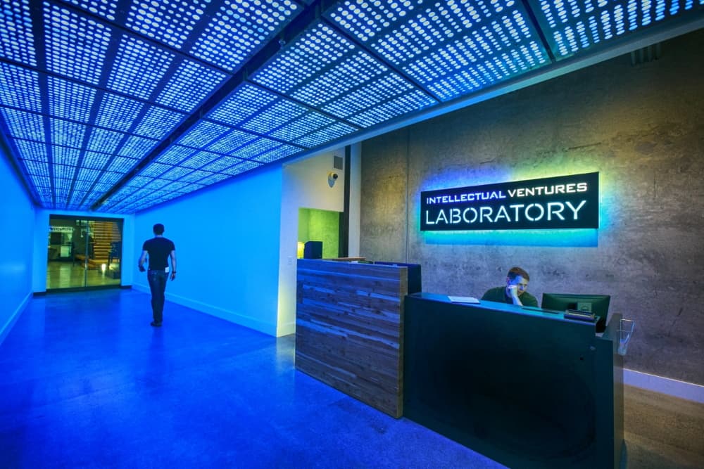
Tenant-improvement electrical for an invention laboratory, including a programmable LED-lit reception environment and the power and controls behind advanced research and prototyping space.
Aerospace manufacturing — tower & facility electrical
Electrical work at a major aerospace manufacturer, including the 4-20G tower and ongoing facility programs across Renton and Everett.
Frequently asked
Questions buyers ask us
What does critical power mean in a data center?
Critical power is the electrical infrastructure whose job is to keep computing and cooling load energized without interruption regardless of what happens upstream. It combines an uninterruptible source that bridges the instant between utility loss and backup generation, a standby generation plant that carries the load through an outage, and a redundant distribution system so any single component can fail or be serviced without dropping the load.
What is the difference between N+1 and 2N redundancy?
N is the exact capacity needed to carry the load with nothing to spare. N+1 adds one extra component beyond need, so any single unit can fail or be serviced while the rest still carry the load. 2N is full duplication, two complete and independent systems each able to carry the entire load, so an entire distribution path can go down with a mirror ready to carry everything. 2N+1 adds a spare component within a fully mirrored architecture.
What is concurrent maintainability?
Concurrent maintainability means any component or distribution path can be removed from service for maintenance or replacement without affecting the load. It corresponds to Uptime Institute Tier III and typically requires N+1 capacity with multiple distribution paths, one active. It differs from fault tolerance, Tier IV, which sustains any single unplanned failure, including a distribution path, without impact even while maintenance is underway.
How does a UPS keep a data center online during an outage?
A double-conversion UPS continuously rectifies incoming AC to DC and inverts it back to clean AC, so the load is always fed from the inverter with zero transfer time when the utility fails. Its stored energy, in batteries or a flywheel, keeps the DC bus alive during the seconds it takes the standby generators to start and accept load, so the transition from utility to generator is invisible to the servers.
Why do data center generators need to be paralleled?
Paralleling multiple generators onto a common bus lets capacity be added, allows a set to be taken out for maintenance or to fail to start without losing the plant, and applies N+1 or 2N redundancy at the generation layer. Paralleling switchgear synchronizes the sets, shares load among them, adds cooling and mechanical load in controlled steps after the critical load is stable, and sheds load automatically if a machine drops.
What are the commissioning levels for data center power?
Critical power commissioning typically proceeds through progressive levels, from component and factory acceptance testing, to installation verification and site acceptance testing of individual systems, to integrated systems testing where the UPS, generators, transfer equipment, and controls are exercised together under simulated load with the utility intentionally dropped. The goal is to prove the redundancy behaves as designed, with measured transfer times and records the operator will keep for the life of the facility.
Bid invitations & estimates
Planning a data center or critical power build?
We work with general contractors, healthcare facilities, developers, and property managers across Washington. Send plans and we'll respond quickly.